The global tech shift towards USB-C is no secret. Nearly every product that once used a property charging method or one of the many previous variations of USB has all in recent years begun a transition over to standardise with USB-C.
Even Apple has shifted all its Mac computers and nearly the entire iPad lineup to USB-C. Despite the fact the company is rumoured to be marking a return to MagSafe chargers in its next update to the MacBook Pro series, all signs point to USB-C remaining as a backup charging option.
There is, however, one major piece of tech that has chosen to omit the now ubiquitous USB-C standard, and that, of course, is the Apple iPhone.
A switch to USB-C on iPhone would mean that pretty much every single piece of tech in your home could be charged either wirelessly or using just a single cable. Pretty neat, huh?
Instead of holding that to merely a fantasy, a talented hardware modifier has used their skills to Frankenstein the world’s very first iPhone with USB-C.
The unique device was first created by Ken Pillonel, a Swiss Robotics student currently studying for their Master’s.
Check out the eleven-ish minute video posted by them explaining the process of exactly how this was done below.
For those who prefer a write-up
Introduction
I’ll try to make this short and straight to the point. Once the project is done, that is when everything fits inside the iPhone, I will release all the knowledge I have accumulated with the methods to reproduce what I’ve done.
The motivations behind the project are simple. I just want an iPhone with USB Type-C on it. Why? Because everything I own has USB Type-C so it would be pretty neat to convert an iPhone too. Have one charger and one cable to charge everything.
How does it work?
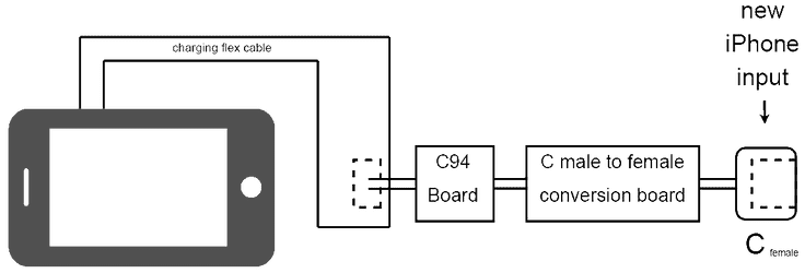
The main idea behind the project is to use a USB-C to Lightning, convert the Type C male end of the cable to a female port and then make the whole thing fit inside the iPhone.
As with any engineering project, I needed to break it done into steps as to actually make progress. The first step is validation that the electronics side can work, regardless of the size of the circuit. Does the Type-C female to Type-C female trick actually work? Well, I bought a breakout board that did this and tested it. Trying to charge with a USB-A to USB-C cable, it works, both ways. I got excited. Then I tried to charge with a Type-C to Type-C cable (an e-marked one, similar to the one to charge a Macbook Pro). It works, but then I try to plug the cable the other way and nothing happens. This means that reversibility doesn’t work that easily and it is definitely a requirement I have for the project. Guess now I have to dig deeper into the cable and find a way to make reversibility work.

After studying the Type-C specification documentation and the internals of a few cables, I found a way to make reversability work. It will be described it in my final write-up. I made a Type-C male to female board and soldered as input of that board the wires coming straight from the Lightning Male side of the cable. The internal connection of the Lightning port is shown in the next diagram, this is important for the next step.

In 2019 Apple opened up the license to the Lightning to USB-C cable to third party manufacturers through its MFI program. The cable used for this project is important. I first tried to open a few Apple Lightning to Type-C (L2C) cables, they are build like tanks. That means it’s very hard to get to the circuit near the Lightning port without breaking it. I then bought a few L2C cables that were certified MFI but not made by Apple. After seeing the circuit on all of them, I realised that they’re all the same and after doing some research it turns out that Apple sells the Lightning connector to the MFI manufacturers for $2.8. Then those manufacturers build the cable around that connector.
This connector is called C94 and the project will heavily depend on it. Note that on the L2C cable made by Apple the connector is called C91 (previously C52), it’s a different circuit. To be able to understand C94 better, I need to be able to solder things on it. The Lightning connector with its metallic part and white resin around the connection pads is very hard to work with. I found a way to remove that part and expose the PCB that makes the whole C94 connector. The result is pictured below, it is the first public picture I found showing this.

Now the next step is to remove the female Lightning port and solder wires straight to the bare C94 board. The type of wire used and its length affect the connection, it’s tricky. Once that was done I had my first working prototype. Lightning is gone and only USB-C is left. My only breakout board had two ports so this is why you see two ports on the picture.


What’s next?
I will need to fully reverse engineer the C94 board to integrate it to my final board that will fit inside the iPhone. The main struggle will be making all fit without losing functionality. Signal integrity will also be a pain.
Quick update [12.10.2021]
The project has been successful! Here is a short teaser while I’m editing the final video. There will also be a write-up on this blog.


